不過礙於MCU應用上來說,週邊設計未必會有顯示器,不像是PC/NB端的方便於顯示.
所以MCU的第一個範例通常最簡單的就是LED(GPIO)控制,就是前面用過的 Example :blinky .
不過在前一篇我們已經在Flash Magic 更新flash中的code實驗裡已經完成UART介面測試.所以我們順著這樣的順序,我們就來測試一下UART的範例程式.
 | |
| (圖2) |
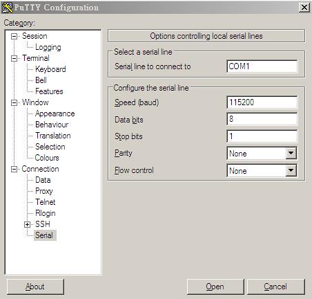
- 開啟putty,選擇你使用的COM port
- 點選Serial ,右手邊Configure the serial line 如圖1設定.
- 按下Open
- 回到LPCXpresso,載入 Project UART後直接build再debug.接著執行.
(圖1)
putty端都沒有顯示任何訊息?
這是當然的,因為仔細看一下code裡面.
int main (void) {
    /* Basic chip initialization is taken care of in SystemInit() called
     * from the startup code. SystemInit() and chip settings are defined
     * in the CMSIS system_.c file.
     */

   /* NVIC is installed inside UARTInit file. */
   UARTInit(115200);

   while (1)
   {    /* Loop forever */
  if ( UARTCount != 0 )
  {
    LPC_UART->IER = IER_THRE | IER_RLS;   /* Disable RBR */
    UARTSend( (uint8_t *)UARTBuffer, UARTCount );
    UARTCount = 0;
    LPC_UART->IER = IER_THRE | IER_RLS | IER_RBR; /* Re-enable RBR */
  }
   }
 }
因為 UARTCount 在遇到while(1)中的判斷時都是0 ,所以這個條件一直都不成立,當然不會有任何UART傳輸的動作.
另外UARTCount 填入任何不等於0的值之後,還是不會在putty上有任何訊息顯示,則是因為 UARTBuffer 內都為0.
所以這裡加上一小段code來完成Hello World!
int main (void) {

/* Basic chip initialization is taken care of in SystemInit() called

* from the startup code. SystemInit() and chip settings are defined

* in the CMSIS system_.c file.

*/


/* NVIC is installed inside UARTInit file. */

UARTInit(115200);


UARTBuffer[0]='H';
   UARTBuffer[1]='e';
   UARTBuffer[2]='l';
   UARTBuffer[3]='l';
   UARTBuffer[4]='o';
   UARTBuffer[5]=' ';
   UARTBuffer[6]='W';
   UARTBuffer[7]='o';
   UARTBuffer[8]='r';
   UARTBuffer[9]='l';
   UARTBuffer[10]='d';
   UARTBuffer[11]='!';

   UARTCount = 12;

while (1)

{    /* Loop forever */

if ( UARTCount != 0 )

{

LPC_UART->IER = IER_THRE | IER_RLS;   /* Disable RBR */

UARTSend( (uint8_t *)UARTBuffer, UARTCount );

UARTCount = 0;

LPC_UART->IER = IER_THRE | IER_RLS | IER_RBR; /* Re-enable RBR */

}

}

}
再build一次,接著按下debug.
完成了.
0 留言:
張貼留言